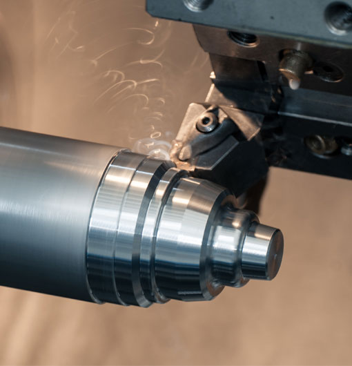
CNC turning is a type of computerized machining process that uses G-code to control and automate the movement of cutting tools. G-code is a programming language that instructs CNC machines on how to perform precise machining tasks like cutting, shaping, or drilling metal workpieces. If you're looking to master CNC turning, having a comprehensive G-code list on hand will be essential to your success. In this blog, we will discuss the most commonly used G-codes in CNC turning and provide example use-cases to help you become more familiar with these crucial commands.
G00 - Rapid Positioning
G00 is used for rapid positioning, which allows you to move a cutting tool quickly to a specified point without cutting the material. This G-code is essential for reducing non-cutting time and increasing productivity.
Example:
G00 X30 Y20
G01 - Linear Interpolation
G01 commands linear interpolation, meaning that the machine moves the cutting tool in a straight line between two specified points.
Example:
G01 X20 Y30 F100
G02 - Circular Interpolation Clockwise
G02 is used to perform circular interpolation in a clockwise direction, meaning that the cutting tool moves in a circle around a specified center point in a clockwise manner.
Example:
G02 X40 Y40 I20 J20
G03 - Circular Interpolation Counterclockwise
G03 performs the same function as G02, but the direction of the circular motion is counterclockwise.
Example:
G03 X50 Y50 I30 J30
G04 - Dwell Time
G04 is used to temporarily pause the CNC machine, allowing you to set a delay before the machine resumes its operation. This G-code can be useful for letting the cutting tool cool down or for waiting for a spindle to reach the correct speed.
Example:
G04 P500
G20 - Inch Units Mode
Setting G20 will change the CNC machine's programming mode to inches, thus interpreting all coordinate values as inches.
Example:
G20
G21 - Metric Units Mode
G21 is similar to G20, but it switches the programming mode to metric millimeters.
Example:
G21
G28 - Return to Home Position
G28 is used to send the cutting tool to the machine's home position, which is often used as a starting point or reference for cutting operations.
Example:
G28 X0 Y0
G40 - Cutter Compensation Off
G40 disables cutter compensation, which means the machine no longer considers the size of the cutting tool when calculating the necessary movements. This G-code is typically used when cutter compensation is not required.
Example:
G40
G41 - Cutter Compensation Left
G41 activates cutter compensation on the left side of the cutting path, taking into account the size of the cutting tool when calculating cutting paths.
Example:
G41 D1
G42 - Cutter Compensation Right
G42 functions similarly to G41 but applies cutter compensation on the right side of the cutting path.
Example:
G42 D1
G70 - Finish Turning Cycle
G70 is a cycle specifically designed for finish turning operations, utilizing a previously defined G71 roughing cycle to complete precise finishing passes in a streamlined manner.
Example:
G70 P1 Q1
G71 - Rough Turning Cycle
G71 defines a rough turning cycle that removes large amounts of material with high-speed passes. This cycle is typically used before a G70 finish turning cycle.
Example:
G71 P1 Q1 U2 W2 F100
G73 - Chip Breaking Cycle
G73 is a cycle that allows for more efficient chip breaking during turning operations. It creates multiple pecking passes to help break chips into smaller sizes, aiding in their removal.
Example:
G73 P1 Q1 R1
G90 - Absolute Positioning
G90 is used to switch the CNC machine to absolute positioning mode, where all coordinate values are referenced from the machine's home location.
Example:
G90
G91 - Incremental Positioning
Opposite of G90, G91 switches the CNC machine to incremental positioning mode, with coordinate values being referenced from the current tool position.
Example:
G91
Armed with this comprehensive G-code list, you are well on your way to mastering CNC turning operations. Don't forget to practice regularly and always double-check your G-code commands to ensure optimal results.
g code list for cnc turning


