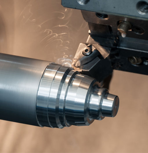
CNC (Computer Numerical Control) turning centres are an essential part of modern manufacturing, providing precision machining and high efficiency in producing complex parts. Understanding how these machines work starts with deciphering their diagrams. In this post, we'll take a closer look at CNC turning centre diagrams and how they can help optimize the machining process.
Introduction to CNC Turning Centres
CNC machines offer a level of automation and precision that outperforms traditional manufacturing methods. CNC turning centres are designed to complete a wide variety of tasks by manipulating workpieces on a rotating spindle. The resulting parts can range in size and complexity, making these machines highly versatile and valuable in multiple industries.
To fully comprehend how these machines function, it's critical to examine CNC turning centre diagrams. These illustrations can help to optimize tool setup, improve overall efficiency, and gain a deeper understanding of the intricacies of the machining process.
CNC Turning Centre Components & Anatomy
A CNC turning centre's primary components include the following:
1. Spindle: The heart of the machine, this rotating component holds the workpiece in place and provides the necessary rotation for the cutting process.
2. Chuck/collet: This mechanism grips the workpiece securely during machining.
3. Tailstock: Used for supporting longer workpieces and can be fitted with a live or dead centre.
4. Turret: Houses and positions the various cutting tools needed for turning, drilling, and milling operations.
5. Slides/axes: Linear slides and axes that allow the precise positioning of cutting tools.
6. Controller: A computer interface that specifies the machine movements and operations according to a programmed set of instructions (G-code).
Decoding CNC Turning Centre Diagrams
Once you know the basic components of a CNC turning centre, interpreting its diagrams becomes simpler. Turning centre diagrams typically include the following elements:
Overhead or plan view: Showcases the machine's layout, including the arrangement and positioning of the spindle, turret, and axes.
Sectional view: Highlights the internal components of the machine, such as the spindle bearings, chuck, and tool holder details.
Tooling layout: Presents information about the required cutting tools, their locations on the turret, and their position relative to the workpiece.
Axis designation and motion: Indicates the X, Y, and Z-axis positions, as well as any additional axes and their respective directions of movement.
Machine specifications: Provides details on crucial aspects like the spindle speed range, horsepower, maximum turning diameter and workpiece length, and axes travel distances.
Electrical schematic: Details the machine's wiring, indicating its control system, sensors, and other electrical components.
Applications of CNC Turning Centre Diagrams
CNC turning centre diagrams can prove useful in a variety of situations. Some of the most common use cases include:
Machine setup: Software-generated diagrams (like those from CAD/CAM programs) can guide operators in setting up workholding components and tooling before a machining job begins.
Operator training: Diagrams help new and inexperienced operators understand the intricacies and workings of a CNC turning centre, making them invaluable teaching aids.
Troubleshooting and maintenance: Should a problem arise with the machine, technical diagrams can provide insight into causes, potential fixes, and proper maintenance protocol.
Process optimization: By visualizing workpiece setups and tool pathways, operators can enhance the overall machining process, reducing cycle time and eliminating errors.
An Ongoing Learning Process
Gaining a thorough understanding of CNC turning centre diagrams requires dedication, practice, and patience. As manufacturing technology continues to advance and evolve, it's essential for CNC operators and machinists to familiarize themselves with new techniques, materials, and best practices in the field. Investing the time and effort to understand these diagrams will ultimately contribute to overall efficiency, quality, and productivity in the manufacturing environment.
Remember that each machine might have slight variations in components, as well as its specific operating procedures. To ensure precision and reliability, always refer to the manufacturer's documentation specific to your CNC turning centre model. Keep learning and refining your expertise in deciphering diagrams, and you'll find yourself well-equipped to handle the challenges and opportunities presented by modern CNC turning technology.
cnc turning centre diagram


