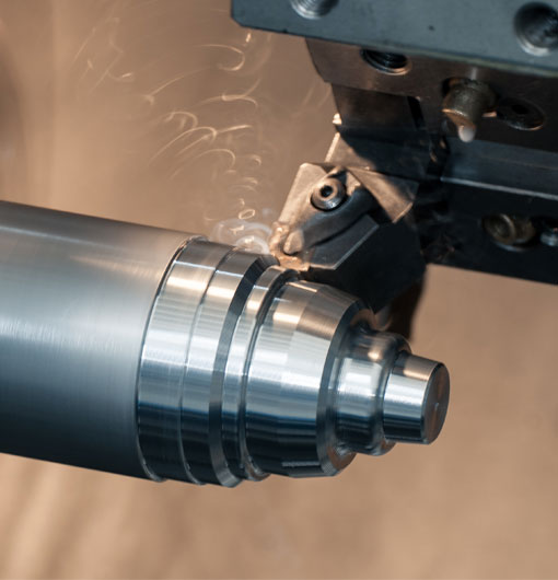
The continuous evolution of manufacturing processes has significantly impacted various industries. Of these advancements, CNC turning stands out as one of the most innovative and advantageous. To fully understand and appreciate this technology's value, one must comprehend the CNC turning coordinate system, the heart of precise part fabrication. This blog post guides you through the CNC turning coordinate system's intricacies, helping you understand its critical role in achieving precision and efficiency in manufacturing.
CNC Turning: A Quick Overview
CNC Turning is a manufacturing process wherein bars of material are held in a chuck and rotated while various cutting tools are precisely driven towards the workpiece, removing material and creating the desired part.
The CNC Turning Coordinate System
At the heart of a CNC turning machine is its coordinate system. This is the reference by which the machine understands where to move the cutting tool to achieve the desired shape. In essence, the coordinate system acts as the language that the machine uses to craft the required parts.
In a CNC turning machine, there are three axes of movement: X, Y, and Z. These three axes form a three-dimensional coordinate system, making it possible for the machine to move in any direction and produce parts of virtually any shape and size.
The X-Axis
In the CNC turning coordinate system, the x-axis describes movement from left to right. If you imagine standing in front of a CNC lathe, the machine moves forward (positive x) when it moves to the right, and backward (negative x) when going towards the left.
The Y-Axis
The y-axis, though less commonly utilized in lathes, describes the movement up and down. Movement up, away from the machine bed, would be considered positive in the y direction, while movement down, towards the lathe bed, would be negative.
The Z-Axis
The z-axis covers the forward and backward movement, much like a standard lathe. In this case, the movement going towards the tailstock is negative (z-) and the movement going towards the spindle is positive (z+).
Traversing the Coordinate System
With these axes defined, the CNC machine can make a variety of movements and cuts in a defined order and consistency. It's often the case that multiple axes will move simultaneously to create more complex shapes. These movements are, of course, guided by the detailed CAD/CAM programs that professionals create.
The Coordinate System in Action
These coordinated movements are essential for creating a variety of features on turned parts. For instance, the machine might use a coordinated x and z-axis movement to create the bevel on the edge of a part. Or it might use a z-axis motion to create a grooving or threading feature. Every different part or feature will require a combination of movements in the x, y, and z directions - all translated into the CNC language by the CAM/CAM program.
The Importance of The CNC Turning Coordinate System
Understanding the CNC turning coordinate system is indeed vital for any business involved in manufacturing. By appreciating the different movements in the CNC lathe's coordinate system, programmers can effectively instruct the machine to produce high quality, accurate results every time.
The CNC coordinate system isn't just about guiding the machine, but also about optimizing its movements. With a better understanding of how these movements work, businesses can find efficiencies, producing more parts in less time - significantly impacting productivity and profitability.
This exploration provides a window into the world of CNC turning and its coordinate system's role in producing precision parts. There's much more to learn, but understanding this fundamental concept serves as a building block for businesses and individuals looking to fully leverage the power of CNC turning machines.
As you continue to navigate the world of CNC turning, remember: the coordinate system is that critical translator, turning designs and ideas into tangible, high-quality products.
cnc turning coordinate system


