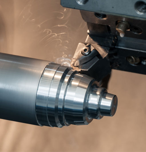
In the world of computer numeric control (CNC) turning, mastering the process of Circular interpolation is crucial. Not merely because it saves time and maximizes productivity, but also because of its sprawling application across various industry sectors.
Circular interpolation, in its most basic form, is the process of cutting an arc or a circle on a CNC machine. While being one of the most common machining operations, it is often met with difficulties due mainly to the complex nature of calculating angles and feedrates. However, with a proper understanding and strategic approach, these complexities can be tamed.
Gearing up for the Circular Journey
Before diving into the sophisticated world of circular interpolation, it*s essential to equip yourself with some vital tools. One of them being - the right CNC machine. The machine's capability to implement circular interpolation is critical in determining the outcome of the process. Also, understanding the machine's software, command language (commonly G-code and M-code) is equally important.
Understanding the Interpolation Technique
Interpolation is primarily of two types - Linear and Circular. While linear interpolation fabricates straight lines and is easier, circular interpolation, the focus of our discussion, is generally used for creating curves and arcs.
In CNC turning, circular interpolation involves two axes moving simultaneously while the tool follows a circular path around a fixed point. This fixed point which functions as the center of the arc is determined by the I, J, and K offsets.
Decoding the G-Codes
Key to mastering circular interpolation is to understand G-codes. The most commonly used G-codes for circular interpolation in CNC turning are G02 and G03. While G02 is used for clockwise or right-hand direction cutting, G03 performs the cutting in a counter clockwise or left-hand direction.
For instance, consider the command G02 X40 Z-30 I-20 K-20 F0.5. In the typical XYZ coordinate plane, this command instructs the machine to carve an arc from its current location, ending at the point (X=40, Z=-30) through a circular path in the clockwise direction, with a feedrate of 0.5 mm per revolution.
Common Challenges and their Potential Solutions
Like any machining technique, circular interpolation too brings its set of challenges. The common issues CNC operators encounter during the circular interpolation process can be broadly classified into four categories: inaccurate radius, wrong feedrates, incorrect start or end points, and limitations of the machine itself.
Addressing these challenges requires two key things - an understanding of the problem and the needed clarification of G-code instructions. It is important to validate the dimensions and specifics with detailed tools such as Coordinate System Diagrams, Radius Dimension Diagrams, etc., while also figuring out the best way to incorporate them into the CNC commands.
One common approach to solve radius inaccuracies is to develop a strategic plan for the moves. Rather than risking large radius jumps within a single G-code command, it could be more effective to split them into several simpler commands.
Takeaways
While a blog on circular interpolation in CNC turning would be incomplete without a brief discussion on challenges and their potential solutions, it*s likewise essential to note that the most reliable solutions usually occur out of practical, hands-on experiences. Understanding circular interpolation requires considerable time and effort, but once mastered, it can tremendously increase productivity and precision.
No formula is definitive and problem-free. It's a process of constant learning and growth. Remember, every mistake is a stepping stone to improvement, and every challenge is an opportunity to innovate. As Al Newton rightly said, "An obstacle is often a stepping stone." So, gear up, embrace the changes, take on these challenges head on, and ride on the journey of circular interpolation in CNC turning.
circular interpolation in cnc turning


