Introduction
Computer Numerical Control (CNC) technology has become an indispensable tool in modern manufacturing, due to its efficiency, accuracy, and customization capabilities. Among the many CNC systems available, Siemens stands out for its advanced, user-friendly programming techniques, which enable manufacturers to optimize their operations for increased productivity and improved results. In this blog post, we will dive into the world of Siemens CNC turning cycle programming through detailed examples, exploring the best practices and revealing the secrets to master this essential skill in the world of precision machining.
The Basics of CNC Turning Cycles
Before we dive into programming examples, it is crucial to understand the fundamentals of CNC turning cycles. These cycles, also known as canned cycles, automate specific machining operations, reducing the amount of programming required and simplifying the overall process.
Turning cycles typically involve a set of standard operations, such as:
1. Roughing:The removal of large amounts of material from a workpiece to bring it closer to the desired shape.
2. Finishing:Precision machining to achieve the specific dimensions and surface finish required.
3. Grooving:Cutting precise grooves into the workpiece, typically for applications like o-ring seals or decorative features.
4. Parting:Separating a finished part from the remaining workpiece material.
Siemens CNC Turning Cycle Programming Examples
To illustrate the power and flexibility of Siemens CNC turning cycle programming, we will walk through several real-life examples, covering various machining operations and highlighting the key programming concepts that can be applied across a wide range of applications.
Example 1: Basic Roughing Cycle
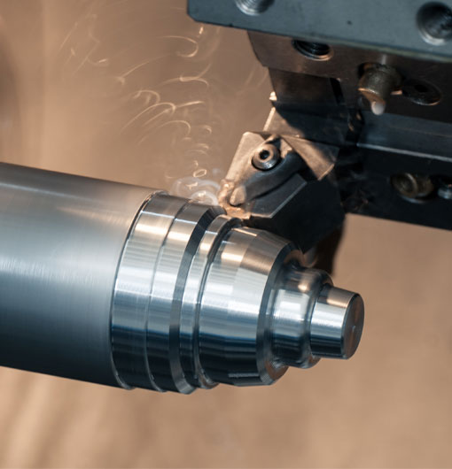
The first example demonstrates a simple roughing cycle, in which we remove material from a cylindrical workpiece to create a step-shaped profile. The relevant Siemens cycle for this operation is Cycle95\_H.
N10 G90 G71 (Set absolute dimensions and work coordinate system)N20 G00 X60 Z2 (Move the tool to the starting position)N30 G96 S200 M3 (Start the spindle with constant surface speed); Roughing cycle invocationN40 G71 U10 R5 (Define roughing allowance and retract distance)N50 G71 P60 Q90 U0.5 W0.2 F0.3 (Link roughing cycle to sections P and Q); Toolpath definitionN60 G00 X50 Z0 (Start of P section (roughing) )N70 G01 Z-45 F0.25 (Cutter plunges and moves left)N80 G00 X50 (Cutter retracts to the safe distance)N90 G00 X40 Z2 (Start of Q section (finishing))N100 G01 Z-45 F0.1 (Cutter moves left with slower feed rate)N110 G00 X40 (Cutter retracts to the safe distance)N120 M30 (End of program)
Example 2: Internal Grooving Cycle
In this second example, we'll perform an internal grooving operation on a workpiece using the Siemens Cycle97\_H cycle.
N10 G90 G71 (Set absolute dimensions and work coordinate system)N20 G00 X60 Z2 (Move the tool to the starting position)N30 G96 S200 M3 (Start the spindle with constant surface speed); Grooving cycle invocationN40 G97 P60 Q100 F0.05 (Link grooving cycle to sections P and Q); Toolpath definitionN60 G00 X50 Z0 (Start of P section (roughing))N70 G00 Z-20 (Cutter plunges to the groove depth)N80 G00 X50 (Cutter retracts to the safe distance)N90 G00 X40 Z2 (Start of Q section (finishing))N100 G00 Z-20 (Cutter plunges to the groove depth)N110 G00 X40 (Cutter retracts to the safe distance)N120 M30 (End of program)
Example 3: Complex Turning Cycle
In our final example, we'll create a more complex turning cycle, incorporating both roughing and finishing cycles to achieve a precise final shape. This operation utilizes Siemens Cycle95\_H and Cycle97\_H cycles.
N10 G90 G71 (Set absolute dimensions and work coordinate system)N20 G00 X60 Z2 (Move the tool to the starting position)N30 G96 S200 M3 (Start the spindle with constant surface speed); Roughing cycle invocationN40 G71 U10 R5 (Define roughing allowance and retract distance)N50 G71 P60 Q90 U0.5 W0.2 F0.3 (Link roughing cycle to sections P and Q); Toolpath definition for roughingN60 G00 X50 Z0 (Start of P section (roughing))N70 G01 X30 Z-45 F0.5 (Cutter moves left and downwards)N80 G01 X10 Z-90 F0.5 (Cutter moves left again)N90 G00 X50 (Cutter retracts to the safe distance); Finishing cycle invocationN100 G97 P110 Q140 F0.1 (Link finishing cycle to sections P and Q); Toolpath definition for finishingN110 G00 X35 Z0 (Start of P section (finishing))N120 G01 X20 Z-35 F0.05 (Cutter moves left and downwards)N130 G01 X5 Z-70 F0.05 (Cutter moves left again)N140 G00 X35 (Cutter retracts to the safe distance)N150 M30 (End of program)
Expanding Your CNC Turning Cycle Expertise
The examples provided in this blog post are just the tip of the iceberg when it comes to Siemens CNC turning cycle programming. By dedicating time to study and practice these programming techniques, you can unlock the full power of precision machining, allowing you to tackle a wide array of applications spanning numerous industries and leading to enhanced productivity and higher quality parts. Embrace the power of Siemens CNC turning cycle programming, and watch your machining expertise soar to new heights.
siemens cnc turning cycle programming examples


