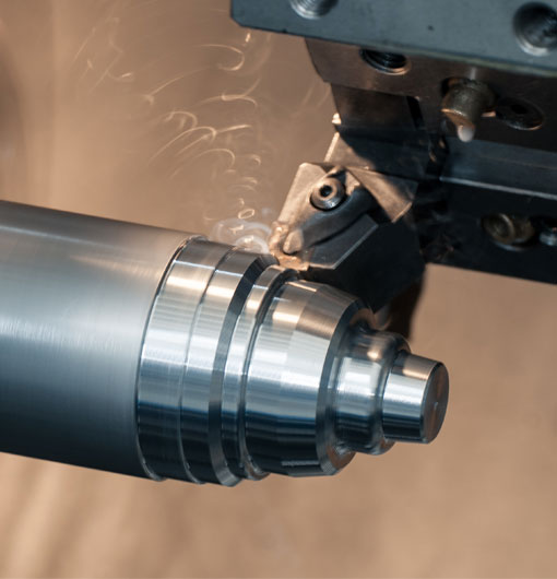
This is a simple diagram showing a turning center for cnc machines. The main components are
1. A spindle motor that turns the workpiece and feeds it to the tool post. It can be either a spindle or a ballscrew, depending on the requirements of the machine
2. A machining centre that positions the workpiece and moves it along its path. It may be mounted on an X-axis drive or clamped to an XY table, and can also be gantry rotary table (GPT) or belt conveyor based systems
3. A tool post that holds tools such as drills, milling cutters etc., which are used in machining operations on parts made from any material that can be machined using CNC tools (such as steel). The tool post may have adjustable height tables so that different heights of workpieces may be machined at once; if this is not possible then different sizes of workpieces may be machined by changing their position in the chamber between operations.
cnc turning centre diagram


