Introduction
Fabricated sheet metal components are an essential part of various industries, from automotive and aerospace to construction and electronics. They are known for their durability, versatility, and cost-effectiveness. Designing and documenting these components requires a deep understanding of the materials, manufacturing processes, and industry standards to ensure high-quality and efficient production. In this blog post, we will delve into the crucial aspects of designing and documenting fabricated sheet metal components, providing you with valuable insights and best practices.
Material Selection
The first step in designing sheet metal components is selecting the appropriate material. Common materials used in sheet metal fabrication include:
Steel: Known for its strength and durability, steel is the most commonly used material for sheet metal fabrication. There are various types of steel, such as mild steel, stainless steel, and galvanized steel, each with its unique properties and applications.
Aluminum: Lightweight and corrosion-resistant, aluminum is a popular choice for applications where weight reduction is essential, such as in the aerospace and automotive industries.
Brass: With its excellent corrosion resistance and aesthetic appeal, brass is often used for decorative components and electrical applications.
Copper: Highly conductive and corrosion-resistant, copper is widely used in electrical and electronic applications.
When selecting a material, consider factors such as strength, weight, corrosion resistance, and cost to ensure the best fit for your application.
Design Principles
To ensure the manufacturability and functionality of your sheet metal components, follow these design principles:
1. Bend radius: The bend radius should be at least equal to the material thickness to avoid cracking or deformation. Larger radii may be required for materials with low ductility.
2. Hole spacing: To prevent distortion, holes should be spaced at least two times the material thickness from the edge of the part and three times the material thickness from other holes.
3. Flanges: Flanges should have a minimum length of four times the material thickness to ensure proper bending and support.
4. Relief cuts: To avoid tearing and distortion during bending, incorporate relief cuts at the corners of bends.
5. Tolerances: Consider the manufacturing process and material when specifying tolerances. Tighter tolerances may result in increased cost and lead time.
Manufacturing Processes
There are several manufacturing processes used in sheet metal fabrication, each with its advantages and limitations:
Cutting: Cutting processes, such as laser cutting, plasma cutting, and waterjet cutting, are used to create the desired shape of the sheet metal component. Consider the precision, speed, and cost of each method when selecting a cutting process.
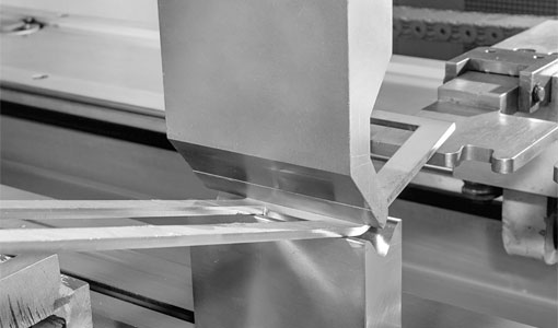
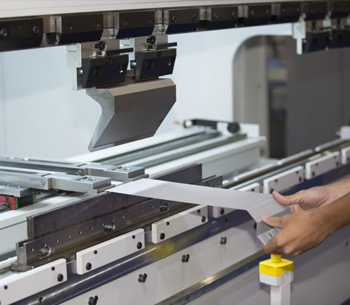
Bending: Bending processes, such as press brake bending and roll forming, are used to create bends and curves in the sheet metal. The choice of bending method depends on factors such as bend radius, angle, and material.
Joining: Joining processes, such as welding, brazing, and riveting, are used to assemble sheet metal components. The choice of joining method depends on factors such as material compatibility, strength requirements, and aesthetics.
Finishing: Finishing processes, such as painting, powder coating, and plating, are used to enhance the appearance and corrosion resistance of sheet metal components.
Documentation
Proper documentation is crucial for the successful fabrication of sheet metal components. Documentation should include:
Drawings: Create detailed, accurate drawings that clearly communicate the dimensions, tolerances, and material specifications of the component. Use industry-standard symbols and notation to ensure clarity and consistency.
Bill of materials (BOM): Provide a comprehensive list of all the materials, components, and hardware required for the fabrication of the sheet metal component, including quantities, part numbers, and descriptions.
Manufacturing instructions: Clearly outline the manufacturing processes, equipment, and tooling required for the fabrication of the sheet metal component, as well as any special instructions or considerations.
Quality control: Establish quality control procedures and inspection criteria to ensure that the fabricated sheet metal components meet the design specifications and industry standards.
Design Software
Leverage the power of modern design software to streamline the design and documentation process. Popular sheet metal design software includes:
Autodesk Inventor
SolidWorks
PTC Creo
Siemens NX
These software packages offer powerful tools for designing and documenting sheet metal components, including parametric modeling, automatic flat pattern generation, and built-in libraries of standard components and hardware.
Continuous Improvement
As with any engineering discipline, the key to success in sheet metal component design and documentation is continuous improvement. Stay up-to-date with industry trends, advancements in materials and manufacturing technologies, and best practices to ensure that your designs remain efficient, cost-effective, and cutting-edge.
In summary, designing and documenting fabricated sheet metal components requires a thorough understanding of materials, manufacturing processes, and industry standards. By following the principles and best practices outlined in this blog post, you can ensure the successful fabrication of high-quality, efficient, and cost-effective sheet metal components.
design and documentation of fabricated sheet metal components


